Autoregulator
Thursday, June 19th, 2025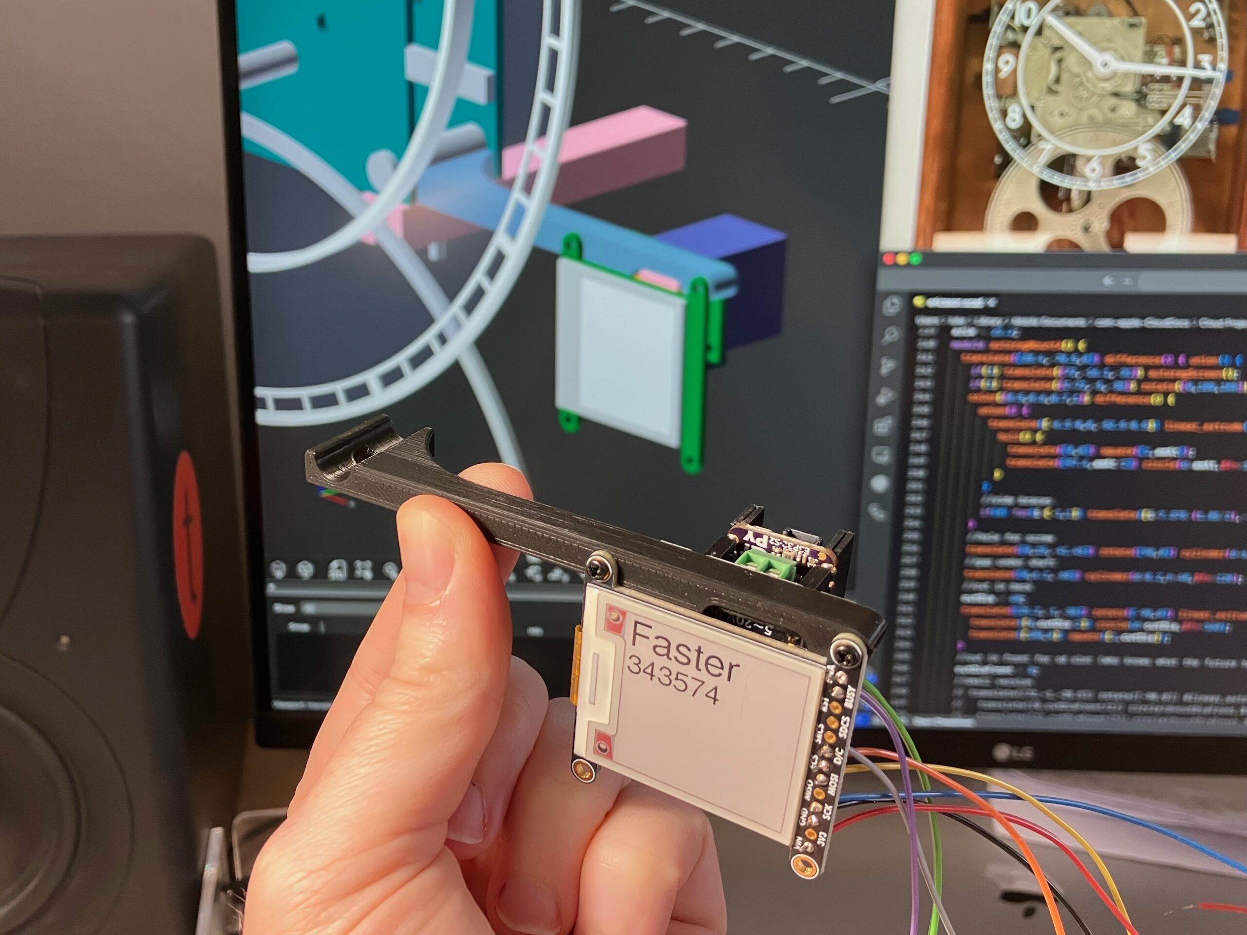
While restoring my Ericsson master clock, I started to ponder whether I could build something to automatically regulate and synchronize it to an external time reference. Inspired by the electric synchronization schemes of the past – and modern solutions like this one – I decided to try building one that mounts a small stepper motor on the pendulum rod to raise and lower a small weight to correct the clock’s timekeeping.
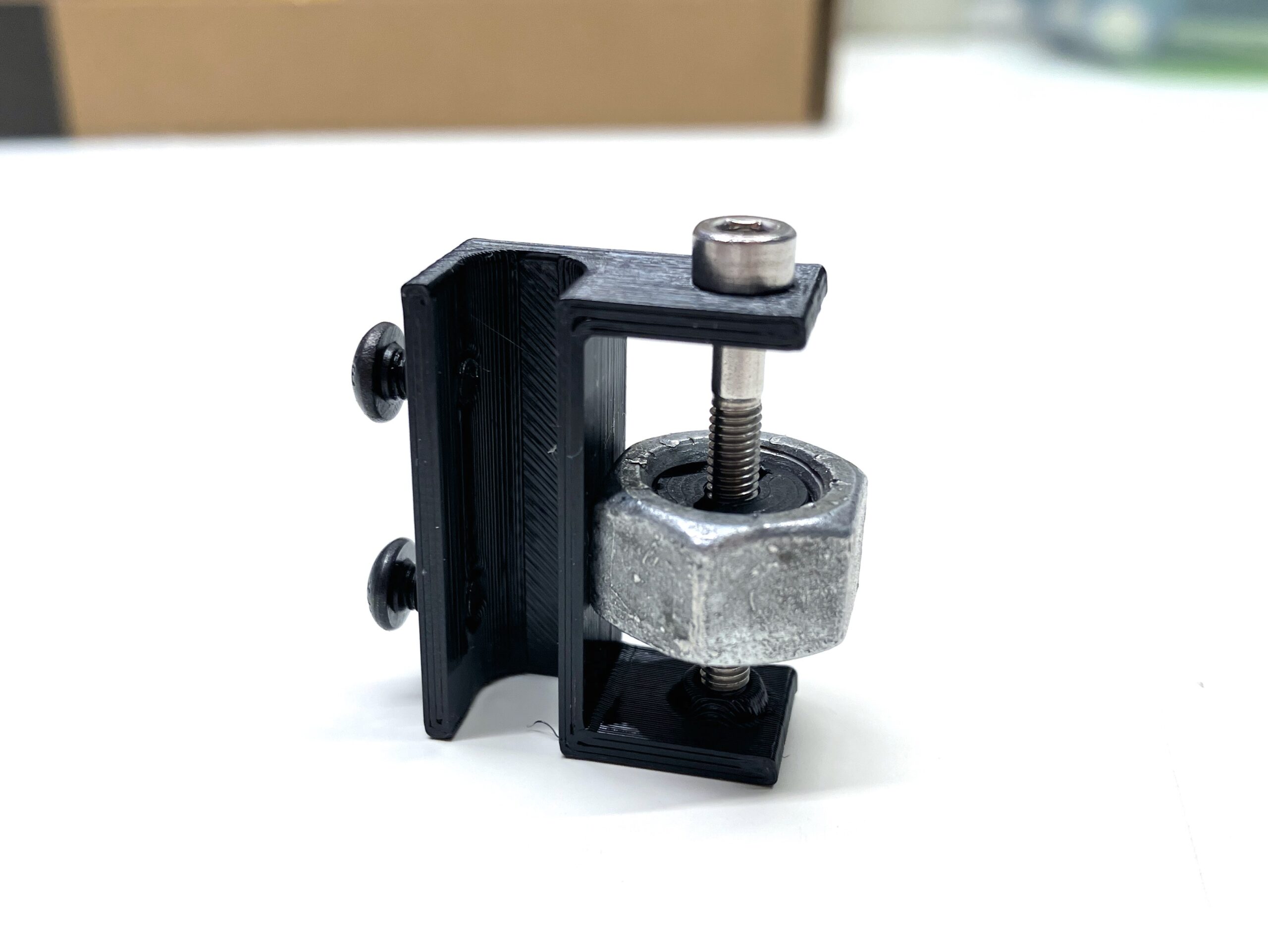
To validate the concept, I 3D-printed a small bracket with a bolt that raised and lowered a heavy nut, to see how much it affected the rate. I figured I would design something to mate a stepper motor to the bolt – and then conveniently found the FIT0708, a micro stepper that comes complete with a threaded rod, and doesn’t even need a hardware driver; it can be driven directly by a microcontroller. This was such an ideal choice that it really got the project rolling.
As for the microcontroller, I had prior experience with the Espressif ESP32, which can be programmed like an Arduino, but has excellent built-in support for WiFi and super-low-power deep sleep – particularly Adafruit’s nifty QT Py implementation – so decided to base the Autoregulator around this.
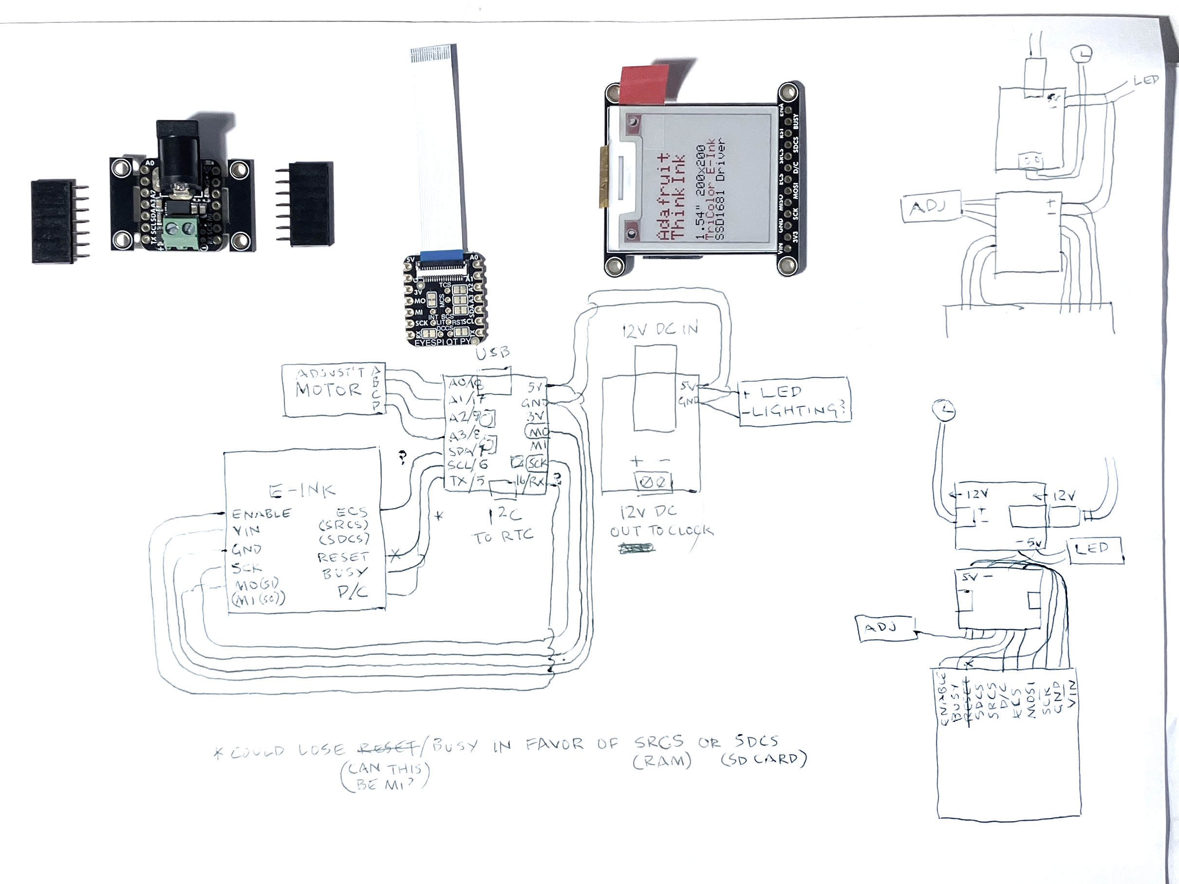
The full list of hardware includes:
- DFRobot FIT0708 stepper motor
- Adafruit QT Py ESP32-S2 microcontroller
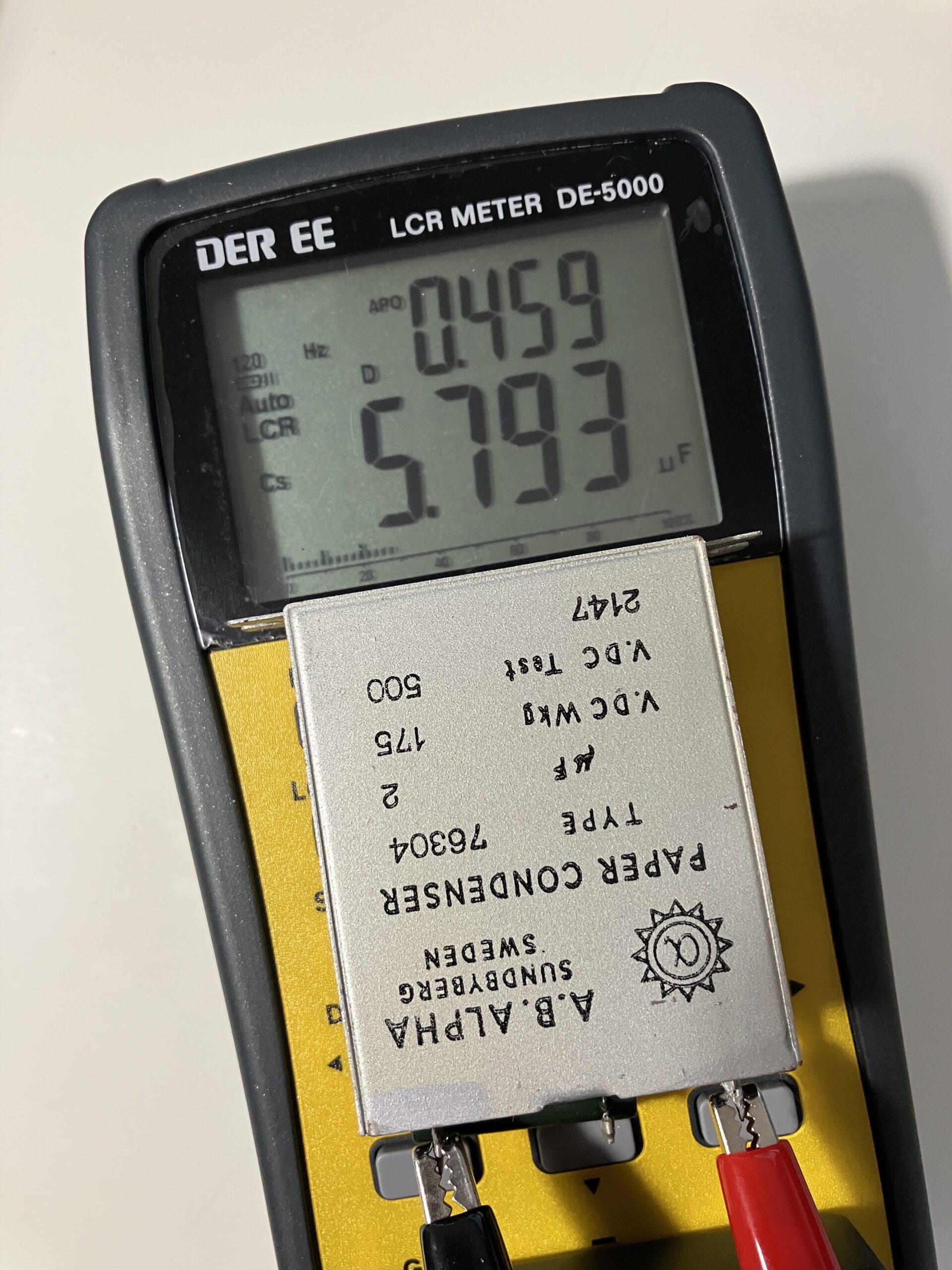
- Adafruit DC Power BFF Add-On, which steps down the clock’s 9VDC to 5VDC for the Autoregulator. As a bonus, its input is wired to both a barrel jack and terminal connectors, so it neatly adapts the power supply’s barrel connector to the clock’s original wiring.
- Adafruit DS3231 Precision RTC, to provide the reference time. This is a real-time clock chip with a thermocompensated quartz crystal, with its own 3V button-cell battery, so it will keep time while the rest of the electronics are asleep.
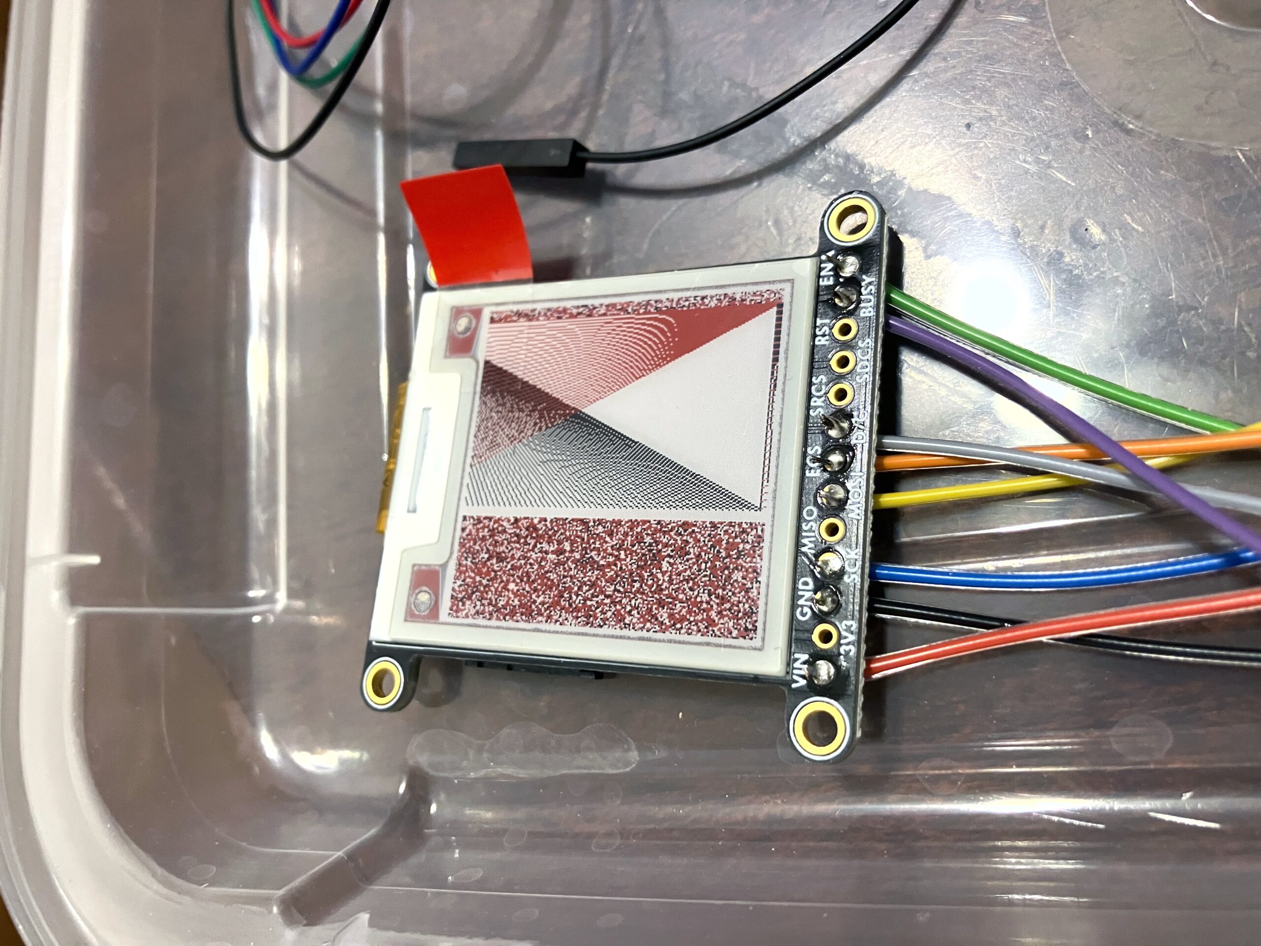
- Adafruit ThinkInk E-Ink display, to give some visibility into what’s going on. E-Ink displays – besides being super crisp – require no power to hold the image, so it’s perfect for this low-power solution that will be sleeping most of the time.
- Adafruit 36AWG wire – more on this later.
The ESP32 will be woken by a hardware interrupt – a connection between a particular pin to either 5V or ground. This could come from something like a magnet closing a reed switch – but as the Ericsson has an unused bell program circuit, it seemed sensible to wire the ESP32 directly to this.
Very luckily, the tiny QT Py ESP32 has just enough inputs to support everything – taking the interrupt trigger from the clock, communicating with the RTC, and driving the stepper and display.
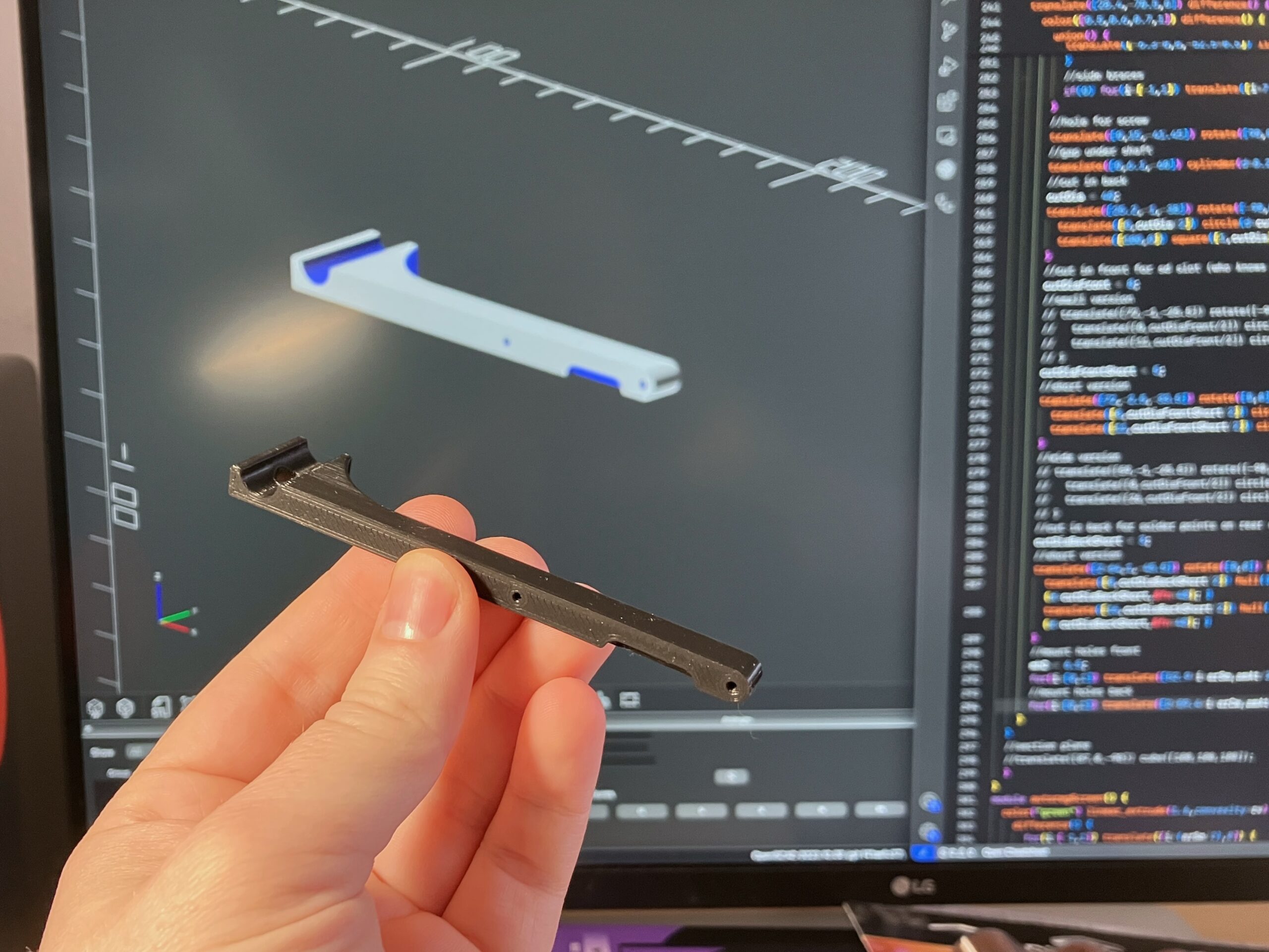
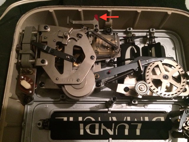
I decided to stack the components and mount them to the lower right of the Ericsson dial, to mirror the old paper condenser on the other side and to be near the original connectors on the right. I didn’t want to add any screw holes, so I 3D-printed a small bracket that sandwiches between the movement’s lower right pillar and its mounting bracket.
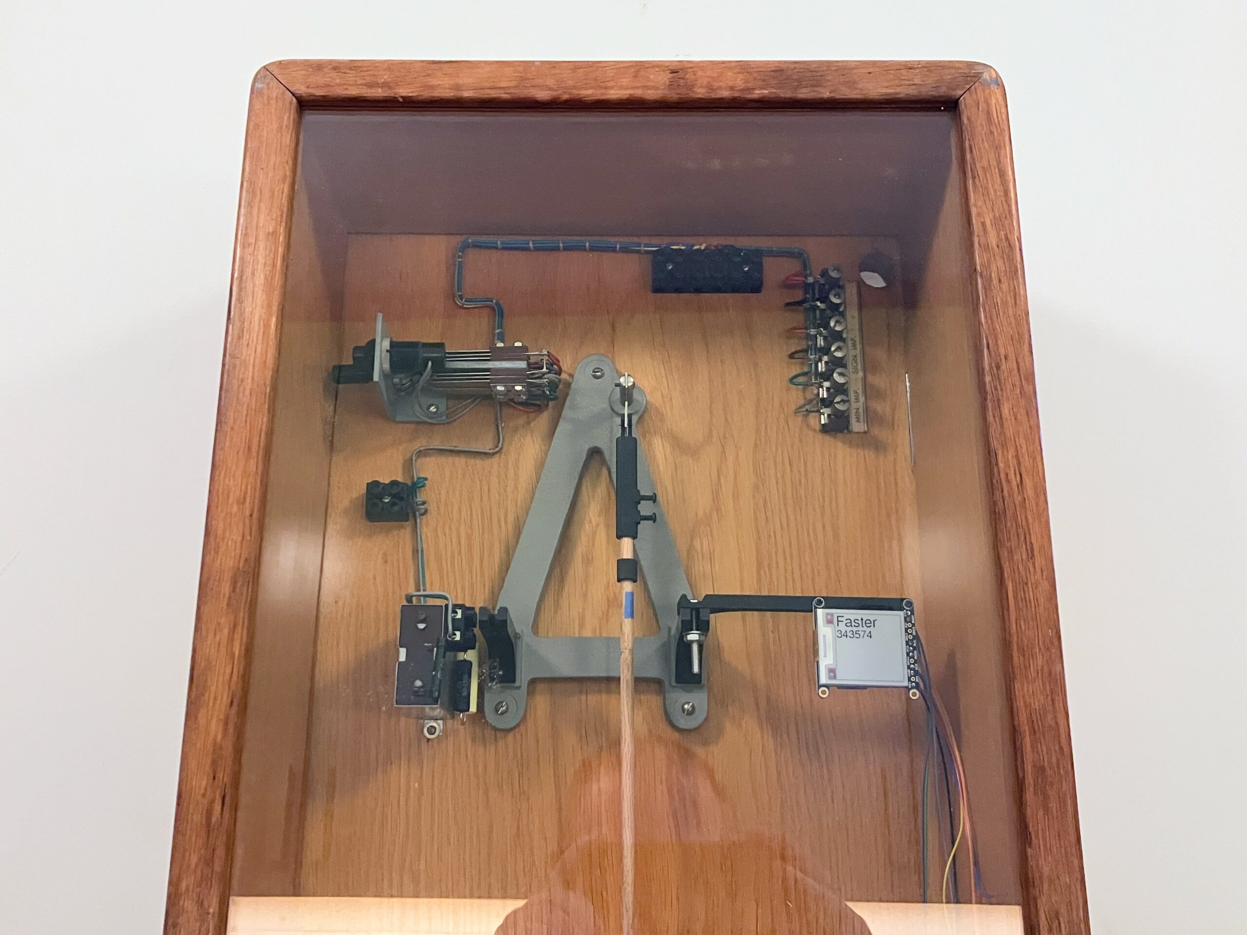
Test fit in the clock.
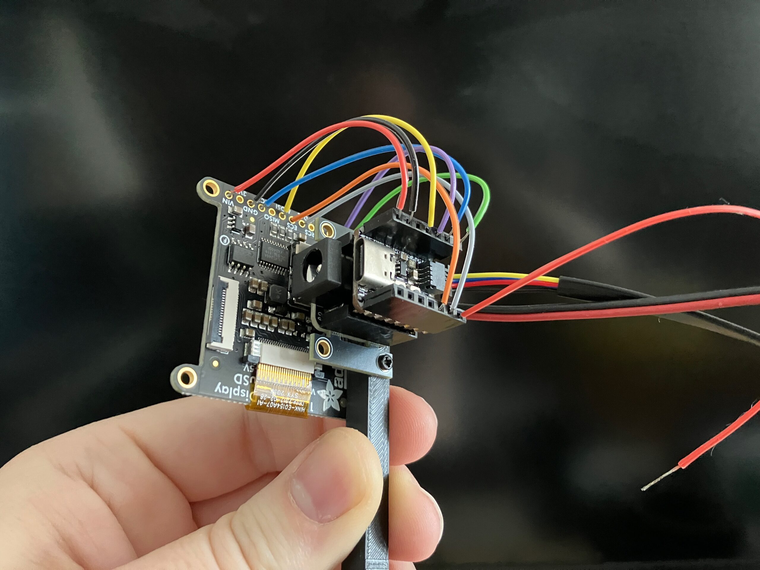
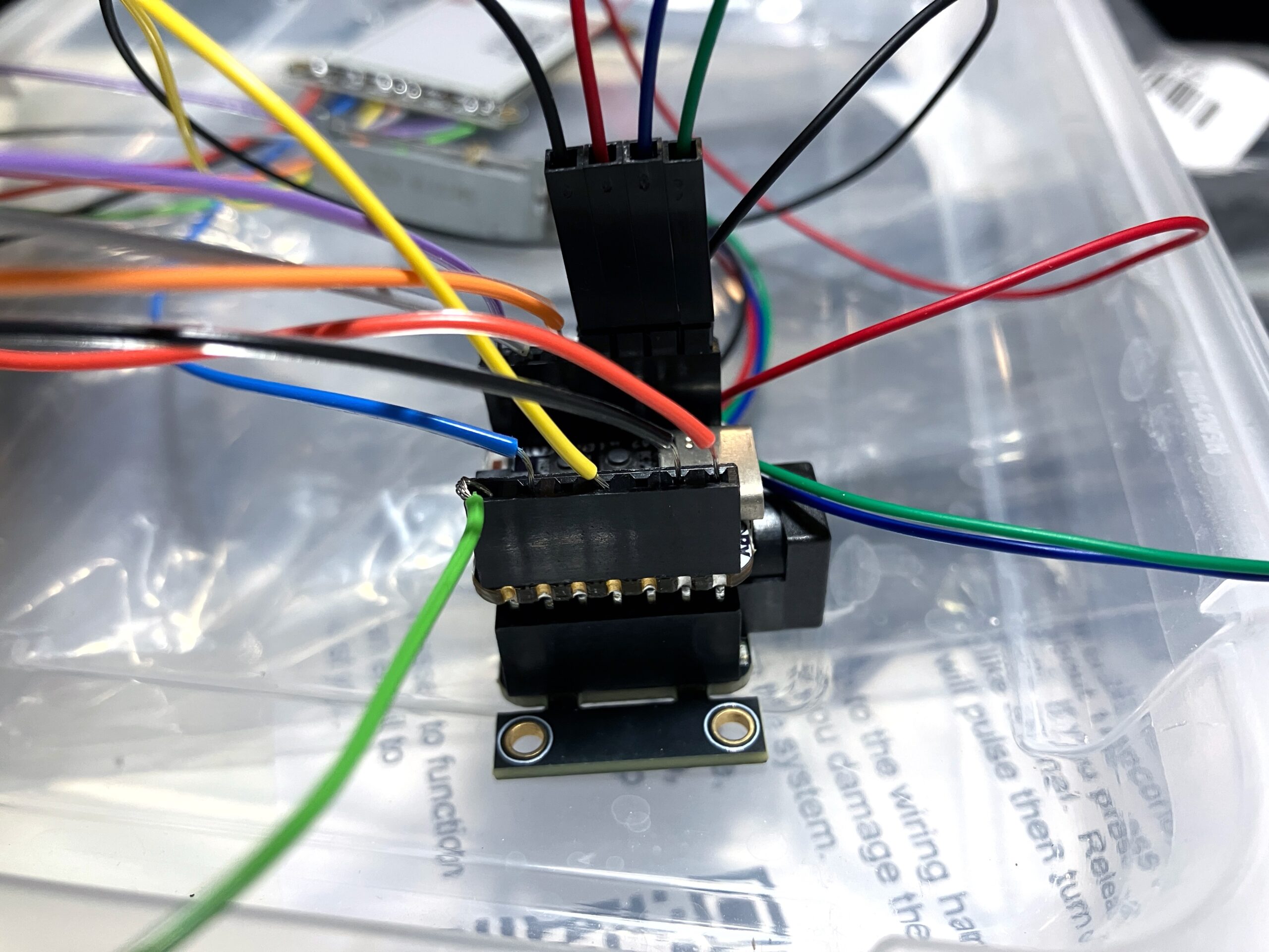
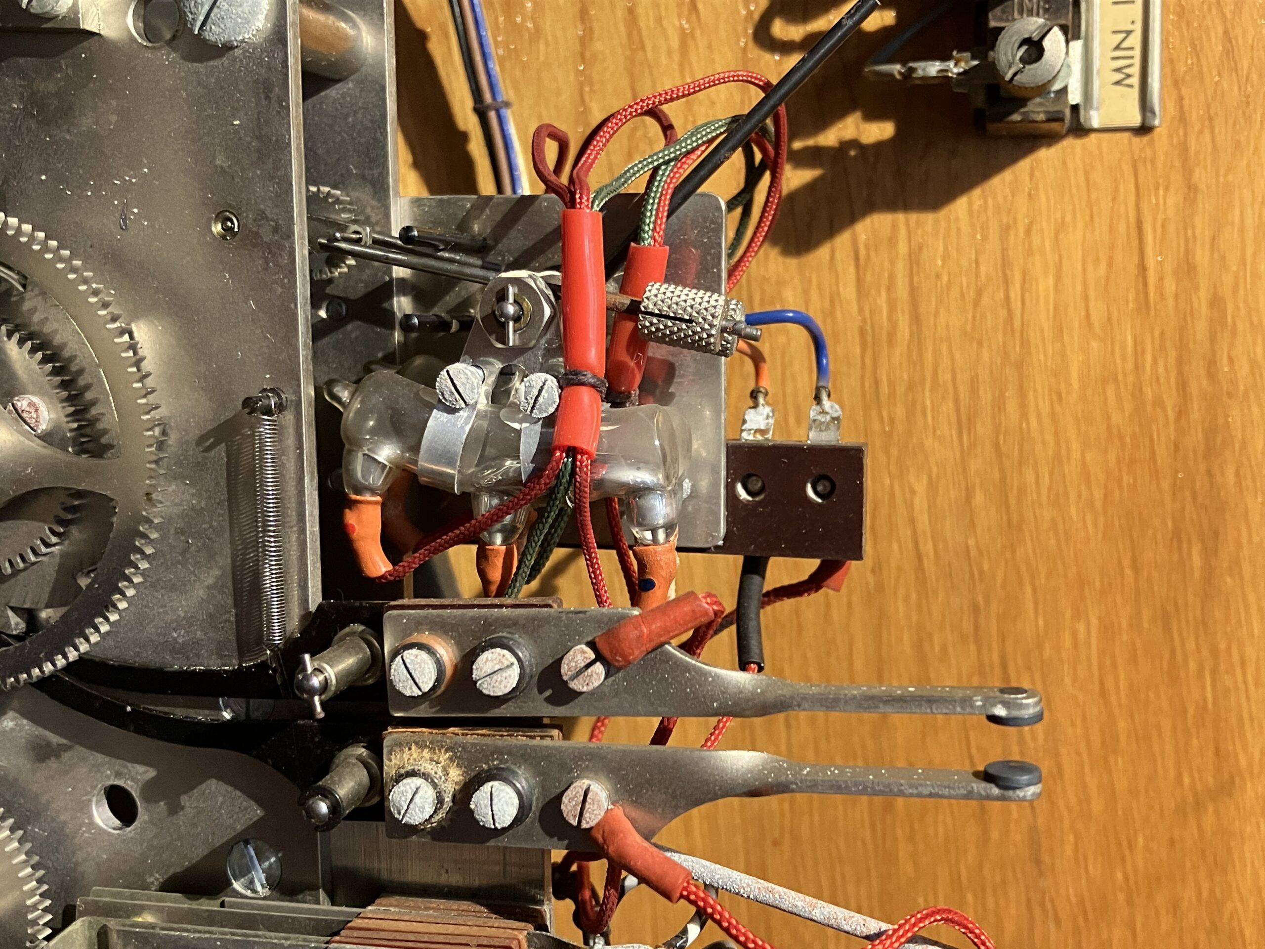
Tidying up the wires. (In time I may solder them directly.)
The Arduino program that runs the Autoregulator is on Github here (and at this writing, still very much in its early stages). With each new trigger, it learns more about the clock and can take further action:
- On the first trigger, it just logs the reference time.
- On the second trigger, it logs a new reference time, compares the two, and calculates the clock’s rate. It also doesn’t yet know how much a given adjustment will affect the rate, so it makes a “test” adjustment to find out.
- On the third trigger, it knows the current rate and the previous rate, and can calculate the “adjustment factor.” From this point on, it knows how much of an adjustment to make to (roughly) get the rate to zero, and will attempt to do this each time.
- Future versions of the Autoregulator will also, at this point, be able to make a temporary adjustment to slowly “set” the clock over the next hour, with the goal of having it synchronized with the reference time by the next trigger.
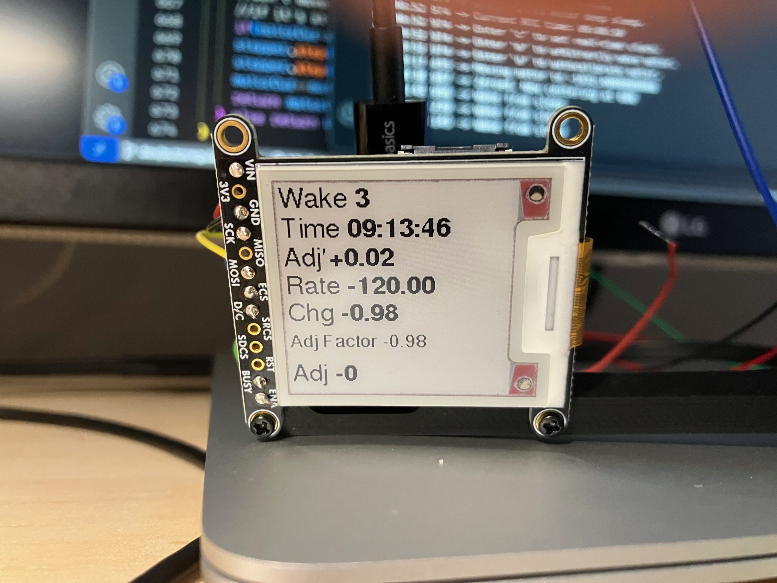
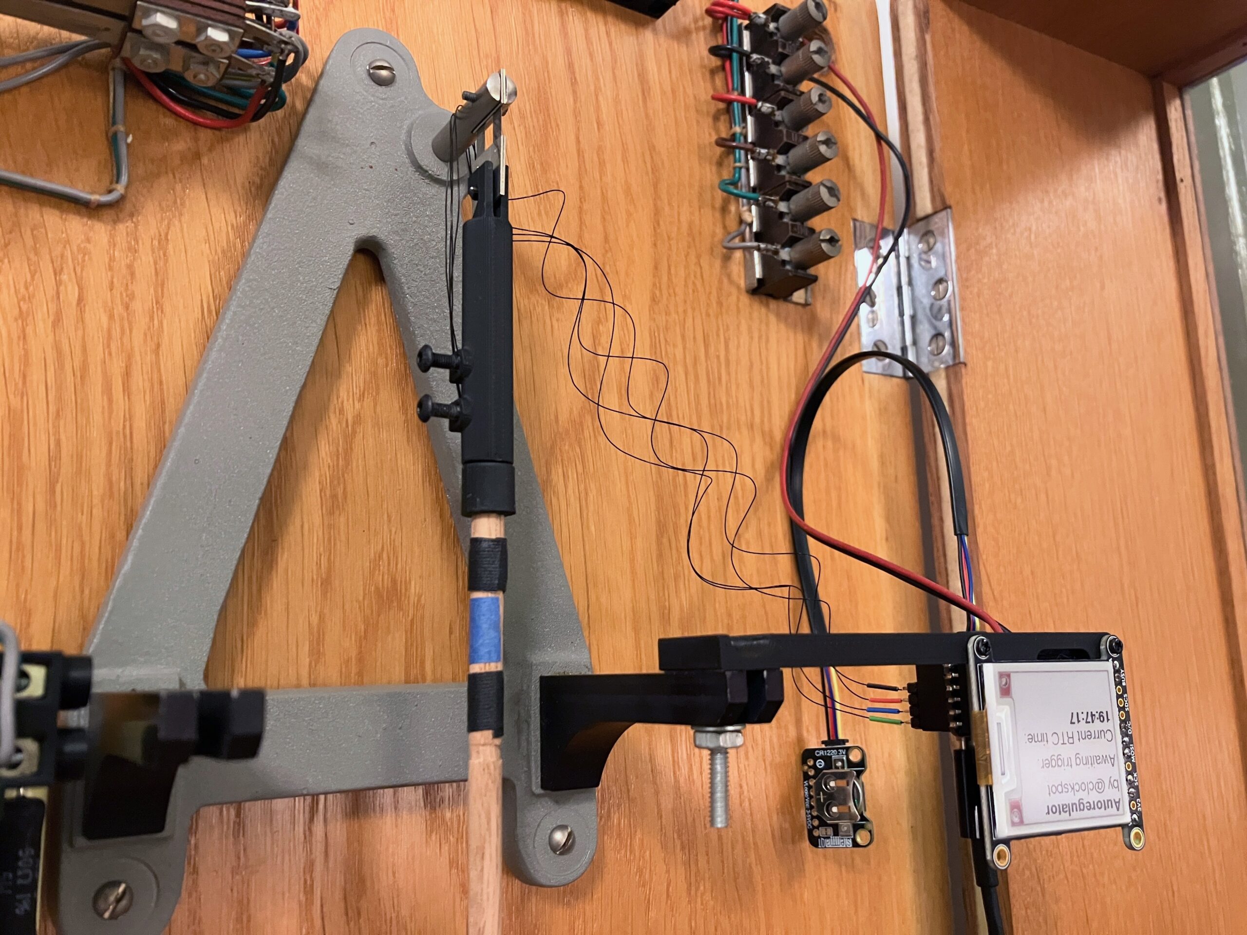
Programming the E-Ink display to show the results of each trigger: the reference time; the last adjustment made; the rate since then; the change in rate; the adjustment factor; and the new adjustment made. (These numbers make no sense due to bugs I hadn’t worked out yet!)
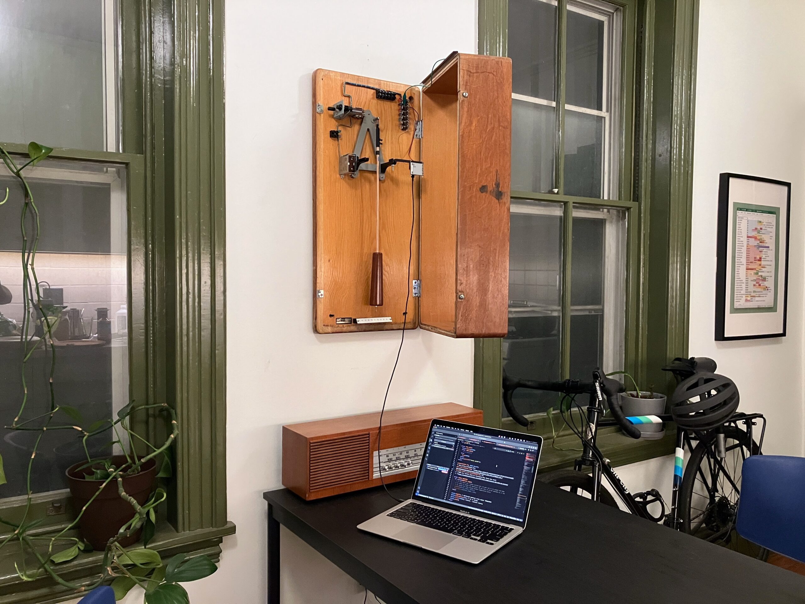
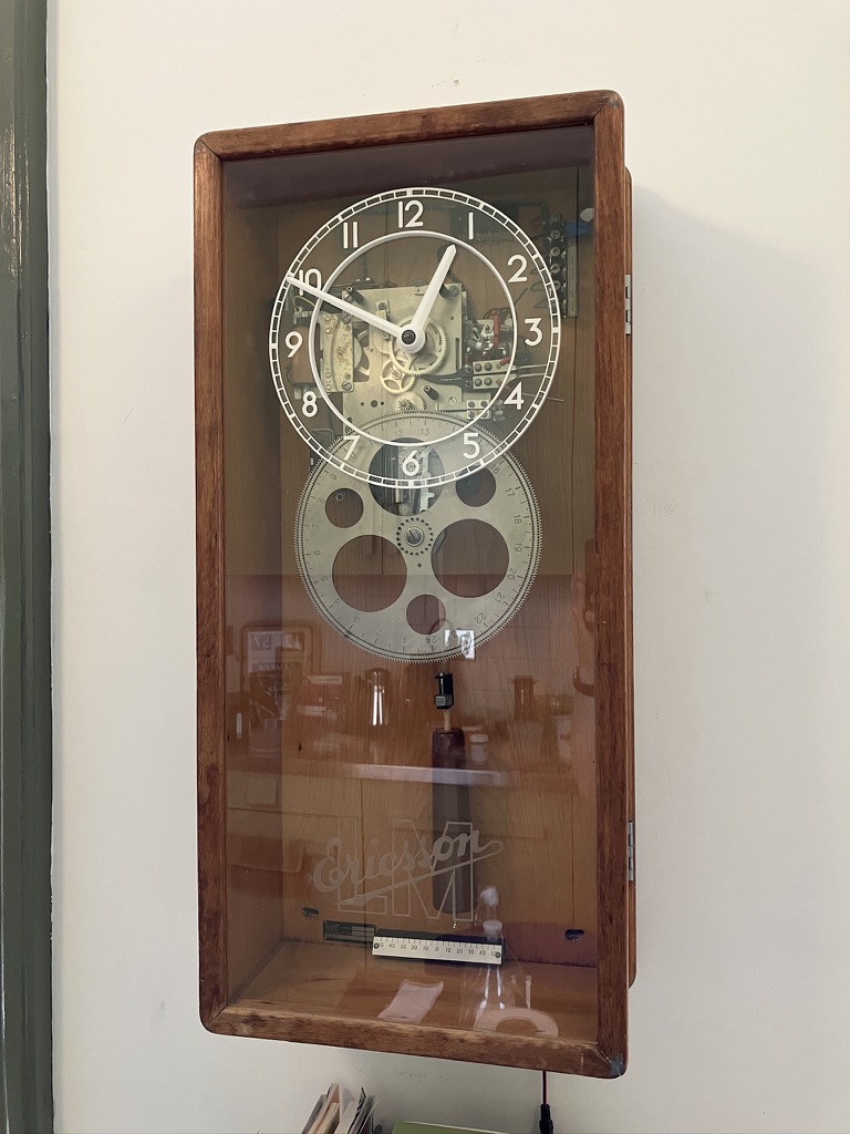
Testing the programming in place.
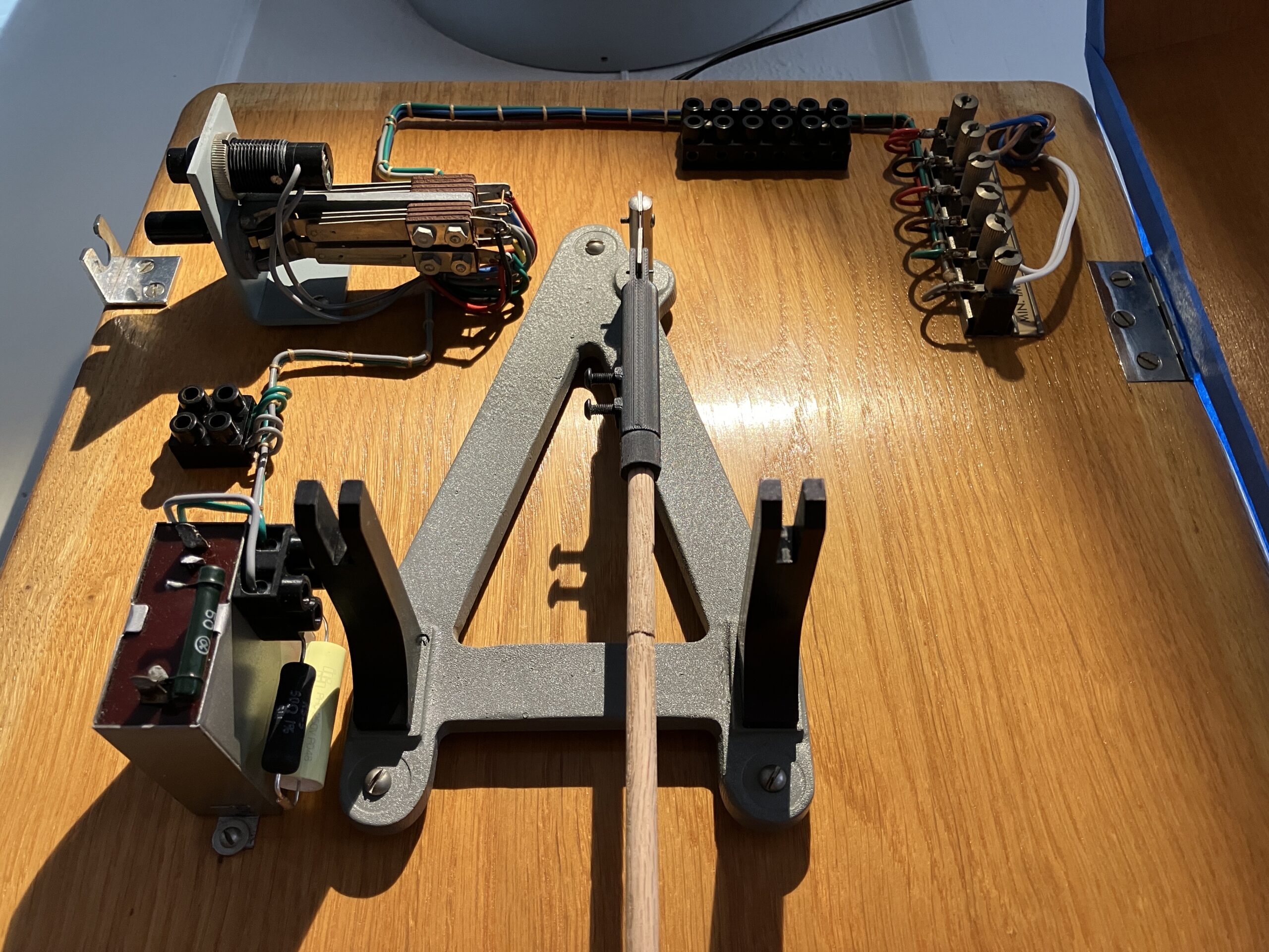
Finally, it was time to connect the stepper motor to the controller. This is the most invasive and fraught step, since it calls for attaching something to the most critical moving piece of the clock – and running wires from it to the stationary controller, with minimal effect on the pendulum’s swing. (This could be averted by designing an Autoregulator that is fully contained on the pendulum rod, battery and all; but it would need to sense the timekeeping from the movement or vibration of the pendulum, which is beyond my chops at the moment.)
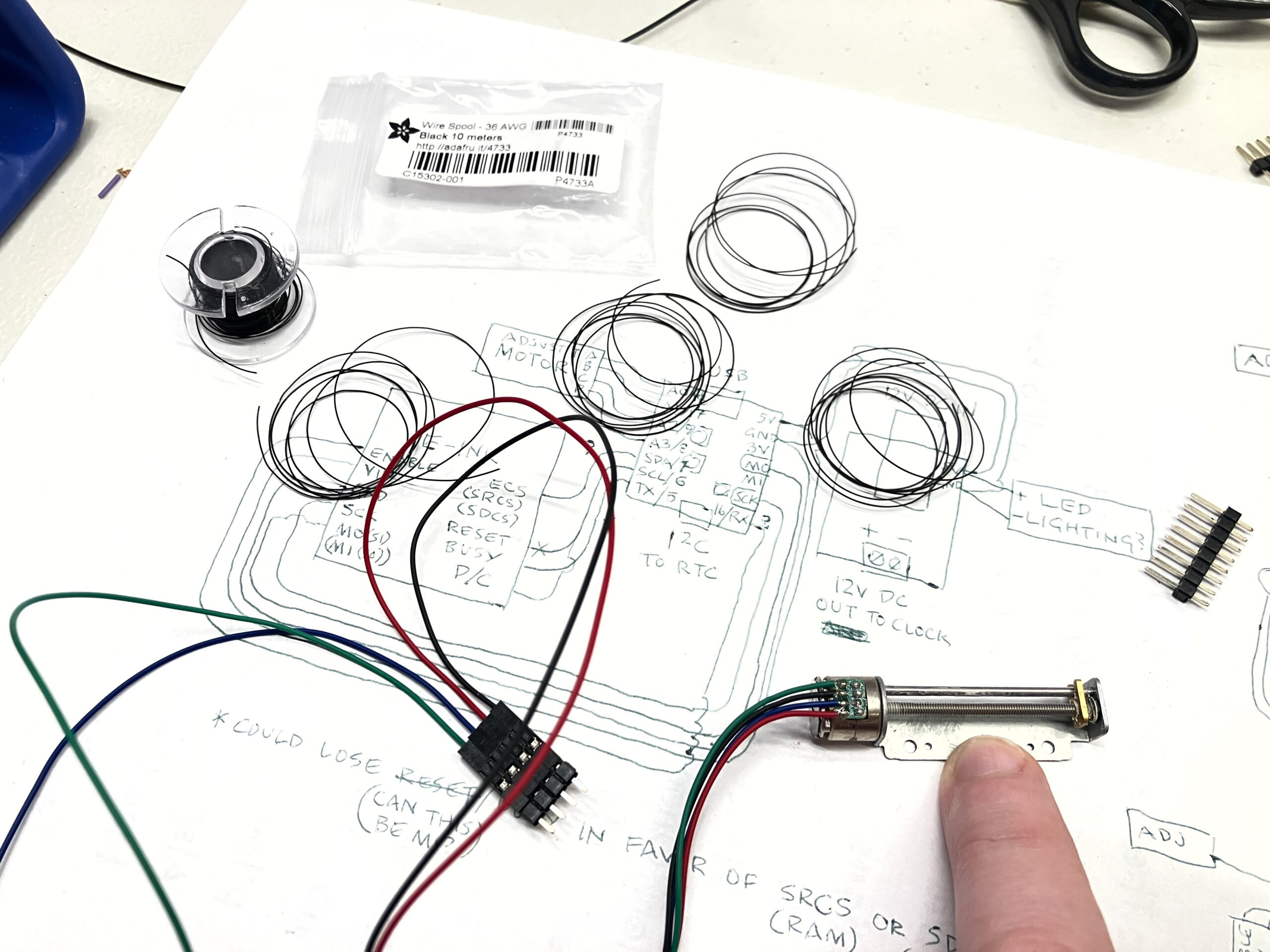
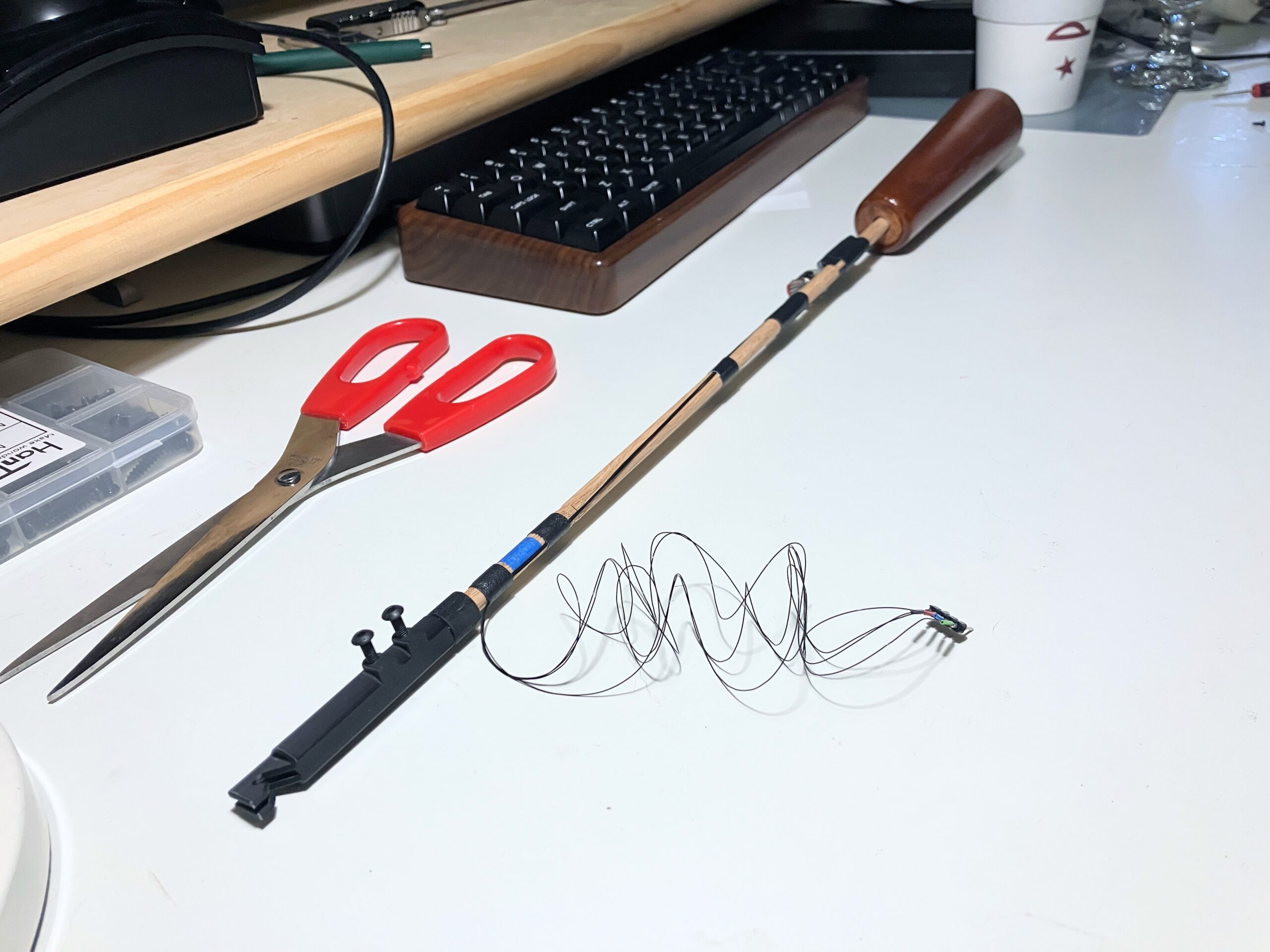
I thought of trying to use the sort of flex cable that’s used to drive the print heads in inkjet printers – but another fortuitous discovery revealed itself: Adafruit’s 36AWG wire. It’s so thin and flexible, it feels like thread. (And it has a bit of precedent in the Ericsson clock, which uses flexible braided wire to connect the moving switches to the fixed terminals.) I decided to try replacing the motor wire with this, and loop it over the suspension spring – the pivot point of the pendulum – to minimize deformation of the wire, and thus any effect it would have on the pendulum’s motion.
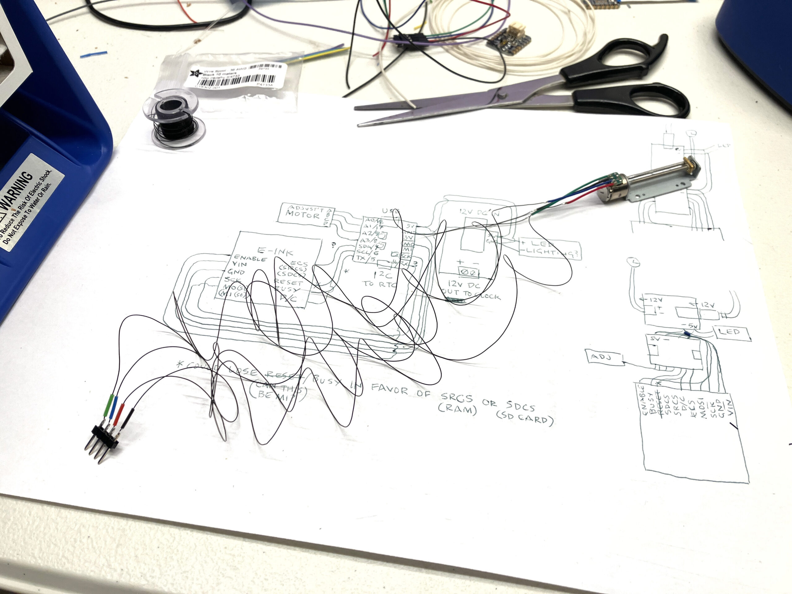
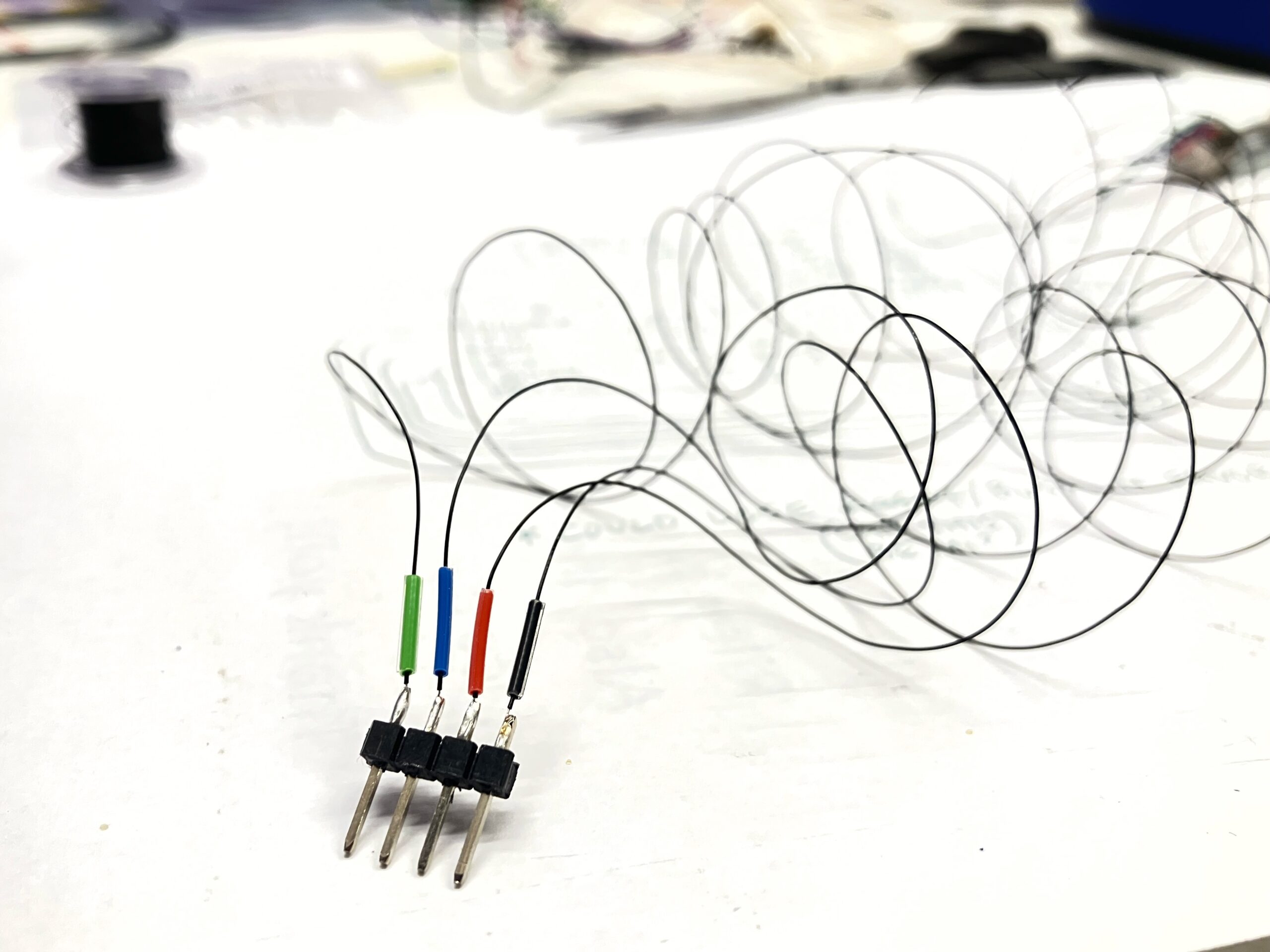
Rather than attempt to solder the 36AWG wire directly to the motor’s tiny daughterboard, I kept a bit of the original wiring, and cut and stripped it in a staggered pattern so there wouldn’t be any cross-contact. I carefully soldered the 36AWG wire to these, and on the other end, to pins to be inserted into headers on the ESP32. The wires are so small that I was able to thread bits of colored insulation from other wires over them, to keep them straight.
I attached the motor and wires to the pendulum with gaffer tape (for the moment). The motor is on the front for demonstration purposes, but the wires run up the back to avoid making contact with the pendulum leader.
Test fit in the clock. It works perfectly, with virtually no interference.
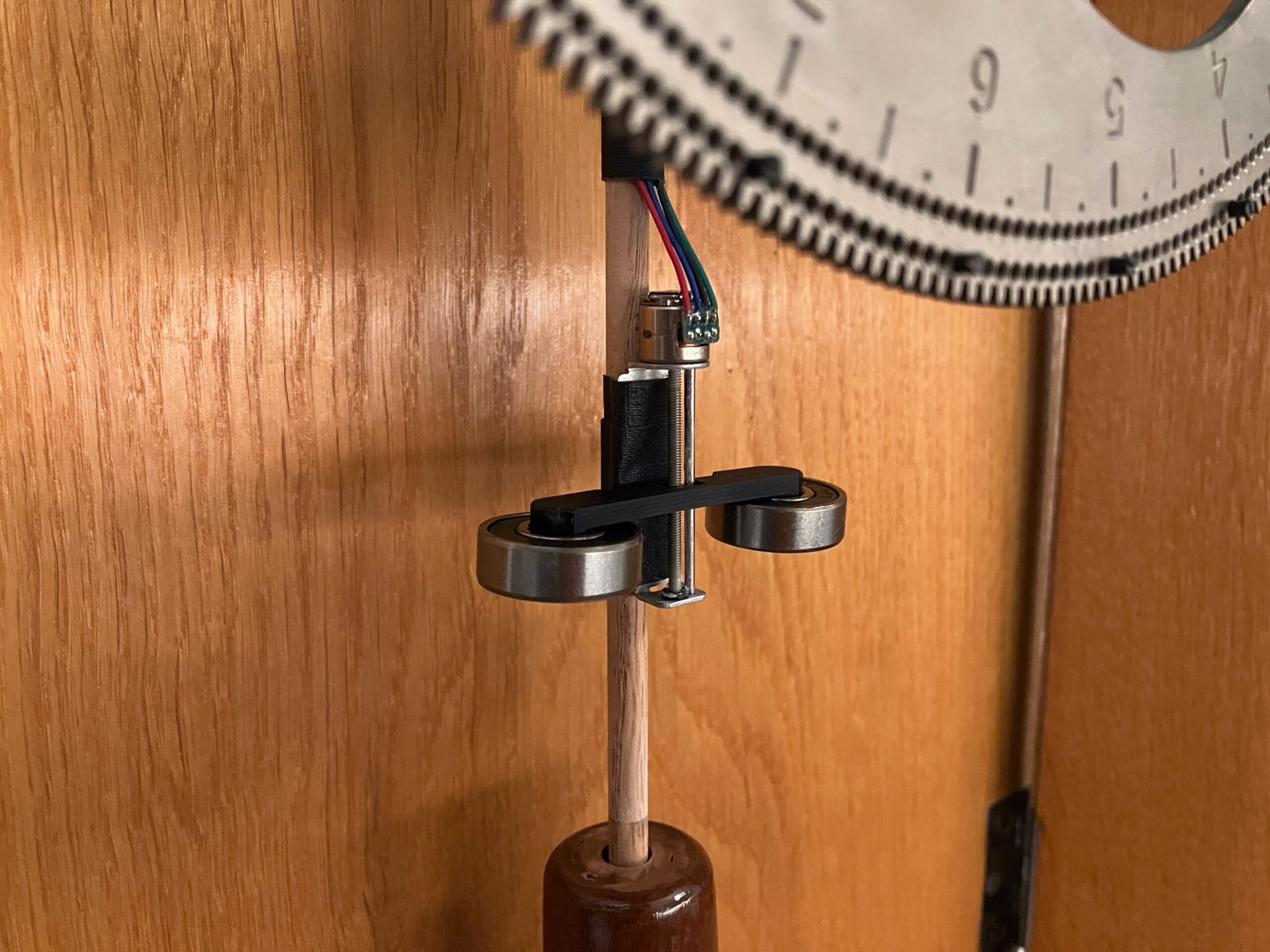
Finally, the small nut on the motor’s threaded shaft needed a bit of weight added to it, to be effective at regulating. So I 3D-printed a quick bracket that holds a pair of bearings – the best combination of small, heavy, and attractive that I had on hand. Then I centered the weights and manually regulated the pendulum to be “close enough” – and in its first integrated test, the Autoregulator did the rest.

Ready for its display at the NAWCC 2025 National Convention craft show!


